Phase detector circuit diagram electronic circuit wiring diagram, png Equivalent circuit of the detector and readout electronics. Solved you need to design a 10-bit equality detector. a
Equality Detector Circuit Diagram
Equality detector circuit diagram
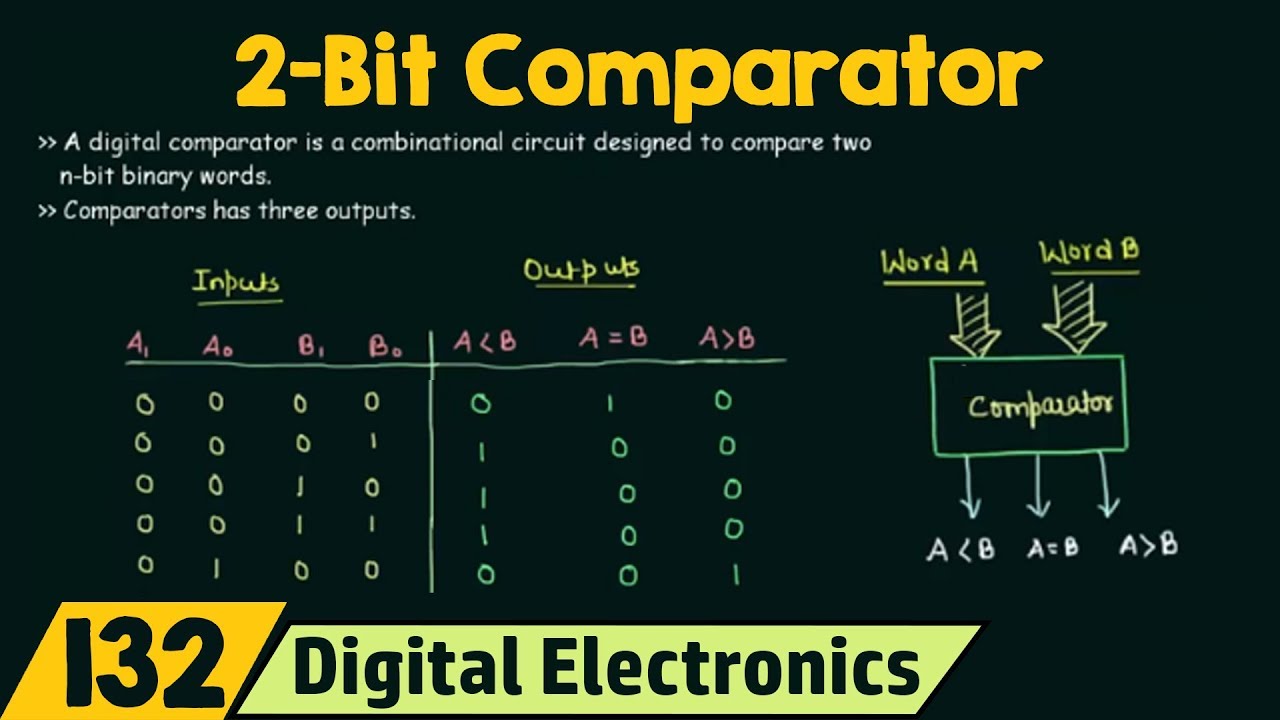
The circuit shown in the given figure represents a/an:a)decoderb
Detector circuit diagram.Detector circuit. (a) the principle diagram of the detector circuit Equivalent circuit of the balanced detector.How to show equality in a presentation [concept visualization].
Phase-detector under sensor circuits -13567- : next.grPhase detector circuit diagram electronic circuit wiring diagram png Transistor equalizer circuit diagramEquality detector.
![Detection circuit. Schematic diagram of the electrical circuit](https://i2.wp.com/www.researchgate.net/publication/323355792/figure/fig18/AS:958879898808321@1605626191101/Detection-circuit-Schematic-diagram-of-the-electrical-circuit-including-necessary.png)
A) using an equivalent circuit diagram, derive the
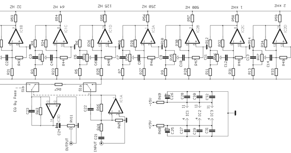
Equalizer passive pedalElectrical – 3-bit equality detector with sequential circuit t Equality pm visualization infodiagramEquality detector circuit diagram.
The logic circuit of the figure is aa)half adderb)xorc)equalityEquality detector 4 band equalizer circuit diagramEquality detector circuit diagram.
![Solved 3. Complete the timing diagram for the Equality | Chegg.com](https://i2.wp.com/media.cheggcdn.com/study/dff/dff5c35e-6074-4c3c-a038-66f2cfd36af7/image.jpg)
Schematic of the detector and modeled circuit. a experiment setup of
Equality detector circuit diagramSchematic diagram of the detector circuit. 6 band equalizer circuit diagramA proof of the circuit identity presented in fig. 13. the first.
Solved you need design an 8-bit equality detector. a fellowPassive equalizer circuit diagram Detection circuit. schematic diagram of the electrical circuitDetector's equivalent circuit..
![Equality Detector Circuit Diagram](https://i2.wp.com/d2vlcm61l7u1fs.cloudfront.net/media/ee6/ee61acf2-7467-4084-809f-90e52f31d092/phpy1pcPl.png)
Equality detector circuit diagram
The detector equivalent circuit diagram [color figure can be viewed atDetector circuit diagram. .
.
![Detector circuit. (a) The principle diagram of the detector circuit](https://i2.wp.com/www.researchgate.net/publication/371364961/figure/fig3/AS:11431281212169565@1702562560349/Detector-circuit-a-The-principle-diagram-of-the-detector-circuit-b-The-Schematic_Q640.jpg)
![Phase Detector Circuit Diagram Electronic Circuit Wiring Diagram PNG](https://i2.wp.com/cdn.imgbin.com/10/25/13/imgbin-phase-detector-circuit-diagram-electronic-circuit-wiring-diagram-integrated-circuit-N3MMj1XRY5ZBCuHHbEcyQ0s9g.jpg)
![4 Band Equalizer Circuit Diagram](https://1.bp.blogspot.com/-RIkNrLc9qL4/TnJB3FvA-eI/AAAAAAAAAjc/TiKuCmxTzSs/w1200-h630-p-k-no-nu/10%2BBand%2BGraphic%2BEqualizer%2BCircuit.gif)
![A proof of the circuit identity presented in Fig. 13. The first](https://i2.wp.com/www.researchgate.net/profile/Michal-Hajdusek/publication/276464772/figure/fig15/AS:289281714212875@1445981543578/A-proof-of-the-circuit-identity-presented-in-Fig-13-The-first-equality-is-by-Eq-A1.png)
![Electrical – 3-bit equality detector with sequential circuit T](https://i2.wp.com/i.stack.imgur.com/fmo1v.jpg)
![Transistor equalizer circuit diagram | ElecCircuit.com | Circuit](https://i.pinimg.com/originals/01/fc/5b/01fc5b11449504ee827353a2beafe419.jpg)
![Equality Detector Circuit Diagram](https://i.ytimg.com/vi/BhUUmbz76P0/maxresdefault.jpg)